Bus Rollover Testing And Simulation
Computational Structural Mechanics Collaborator Research Highlights — Florida State University & Florida Department of Transportation
Current research conducted at FAMU-FSU College of Engineering pertains to comprehensive crashworthiness and safety assessment of a paratransit bus on a Chevrolet 138" wheelbase. The design process of passenger compartment structure in paratransit buses is not regulated by any of crashworthiness standards. FAMU-FSU College of Engineering and Florida DOT work jointly for over a decade on development of a safety and testing standard for the paratransit buses purchased by the state of Florida. Bus rollover test (per European Union Regulation 66) and side impact tests are the subject of their standard. Figure 1(a) shows a photo of an actual bus and (b) the detailed FE model containing 482,812 elements.
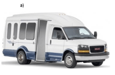
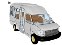
Figure 1. A transport paratransit bus: a) real bus and b) finite element model.
The rollover procedure requires that a vehicle resting on a tilting table is slowly rotated on the weaker of its sides. When the center of gravity (CG) reaches the critical position, gravity causes the bus to free fall into a ditch that has a concrete floor placed 800 mm (31.5 in) beneath the tilt table horizontal position. The simulated test setup is shown in Figure 2. Maximum deformation in respect to the so called residual space is measured in the test. The residual space is a part of the bus interior that needs to be preserved during the impact in order for the bus to pass the test. Figure 3 presents final deformations in the structure of the bus model as a result of the rollover induced impact.
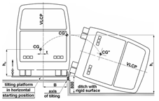
Figure 2. Rollover setup
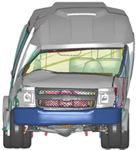
Figure 3. Deformed body after rollover simulation
A second simulation, the simulation of the test side impact test was conducted using the setup shown in Figure 4. The stationary bus is hit by the IIHS movable barrier (Insurance Institute for Highway Safety) moving with the initial velocity of 48 km/h (30 mph). The IIHS barrier represents commercial SUV car and was selected for the test as the highest among all the barriers.
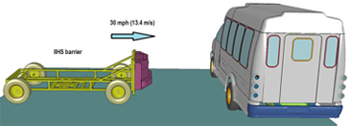
Figure 4. Side impact test initial conditions
An open source FE model of the barrier developed by the LSTC (Livermore Software Technology Corporation) was used in the computer simulations. The barrier model consisted of 118,476 elements, which yields an overall number of 501,288 elements in the model. The results of the simulation are shown in Figure 5.
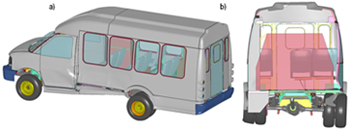
Figure 5. Deformed bus after 30 mph side impact simulation: (a) isometric view and (b) cross section view.
Around 20 LS-DYNA® simulations were performed on the TRACC cluster by FAMU-FSU College of Engineering in the last quarter. Each simulation used 8 nodes (32 cores) and ran for approximately 60 hour time period.
Contact: This email address is being protected from spambots. You need JavaScript enabled to view it. – Computational Structural Mechanics Engineer